Saturday, December 19, 2015
Wednesday, October 21, 2015
Gear Design
For a class project, I wanted to dip my toes into generative CAD, and try to mimic organic growth. However, I Realized that even if I could formulate a method to do so, I would still get riddled with syntax errors. To simplify the task, I figured it would be easier to try to draw something with a defined shape.. So, I chose to parametrically draw gears with involute teeth profiles.
Gears
are devices which transmit circular motion, and they are used just about everywhere. Gears today appear in cars, toys, clocks, any the majority of anything else that has spinning parts. In
ancient history, and even in nature, The desire to transmit and
modify circular motion is ever apparent.


Right, the Antikythera
mechanism is estimated to date to around
200bc, and is comprised of 30 brass gears. Middle, the Isus bug uses
gearing to transmit torque in it's legs while jumping. Left, an
example of a crude gear with simple interlocking pins. In 200bc, a
collection of brass gears was indeed an example of phenomenal
engineering and craftsmanship. However, such gears can now be found
in a child's wind-up toy. As a need is developed for specific gears,
we have found ways to efficiently produce the needed gear. The
following is a discussion of the modern standard in gearing, the
involute profile.
The
Involute Profile
Gears
appear in all sizes and styles, with each being suited to a specific
purpose. No matter the purpose of the gear, the designer has
longevity and smooth operation in mind. While a gear from a car
transmission will be very different from a gear in a watch, they hold
the involute profile in common. The magic
of the involute profile is to allow interlocking teeth to roll off of
each other, rather than shearing. Shearing action under heavy load
will lead to the gears wearing down and eventually failing.
A good
place to start in describing the anatomy of an involute gear is to
imagine two circles that roll on each other without slip. These are
essentially gears minus the teeth. Once teeth are added, this circle
is called the “pitch circle” and is the circle on which the gear
teeth are always making contact. the illustration below details relevant measurements.

As
seen, the teeth are always contacting along the pitch circle. The
next important dimension is the pressure angle. Pressure angle is the
angle between a tangent to the pitch circle at the point of contact
and the line on which the teeth mesh. A higher pressure angle leads
to thicker teeth. After determination of the pitch circle diameter
and the pressure angle, the base circle can be calculated as:
Once the base circle is calculated, It can be used to sketch the involute profiles. An involute profile is the profile obtained when a string is unwound from a cylinder, and the tip of the string is traced.

For a counterclockwise arc,
For a
clockwise arc, values of t have their signs reversed. For different
start points around the circle, the offset is added to t.
This
allows a mat lab function to be created that takes the number of
teeth, the pressure angle, and the modulus. The modulus and the
number of teeth are used to create the pitch circle, then the base
circle is calculated and involute profiles are sketched off of it.
The tricky part is knowing when to start and stop sketching the
profile, and then adding corresponding top lands and fillet radii.
results
from the created matlab function are shown for an 8, a 20, and a 50
tooth gear with pressure angle of .35 radians. The green circle
represents the pitch circle.


he
result of drawing equation driven involute gears gives accurate
results, but takes many piecewise defined parts for the program to
function. The same principle can in theory be applied to
non-circular gears, but finding the end points for drawing the
involute curves becomes very complex.
Below is the Matlab code. It takes input for modulus, Number of teeth, Pressure angle (in radians), and resolution of the drawing (as a fraction).
function [ output_args ] = Geardrawd( modulus,N, PA,res)
%UNTITLED4 Summary of this function goes here
% Detailed explanation goes her
theta=0:res:2*pi;
offset=0; %offset is the angle between centers of gear teeth.
thetasize=size(theta); % This is done to determine the size of the theta vector, so that a radius vector of the same length can be made for plotting.
pitchrad=N./(2.*modulus); % Determines the pitch radius.
basrad=pitchrad.*cos(PA) % Determines the base circle radius. The base circle radius is the radius that all the involutes are "unwound" from.
addendum=1/modulus; % The addendum is the distance from the pitch diameter to the top of the gear tooth.
dedendum=1.25/modulus; % The dedendum is the distance from the pitch diameter to the "well" of the gear tooth.
baseradius=ones(1,thetasize(end)).*basrad; %sets up the base radius as a vector matched in length to theta.
pitchradius=ones(1,thetasize(end)).*pitchrad; % Sets up the pitch radius as a vector matched in length to theta
outrad=ones(1,thetasize(end)).*(pitchrad+addendum); %determines the radius of the outside edge of the teeth.
rootrad=ones(1,thetasize(end)).*pitchrad-dedendum; % Determines the radius of the lowest spot in the well.
alpha=((((2.*pitchrad).^2)-((2.*basrad).^2)).^(1/2))/(2.*basrad)-PA % alpha is a weird one. it is the angle between where the involute intersects the pitch circle to where the involute intersects the base circle.
osos=(2.*pi)/(4*N)-alpha; % osos, standing for "offset offset" is the angular distance from the center of the tooth to where the involute intersects the pitch circle. by subtracting alpha, we determine the angular distance between the center of the tooth and the point of unwinding on the base circle.
filletrad=(basrad/(1.3*N)) % Determines radius for fillet circle
filletradius=(ones(1,thetasize(end)).*(filletrad))+rootrad; %fills in fillet circle matrix.
drawthetabegin=((((filletrad+rootrad).^2)-((basrad).^2)).^(1/2))/(basrad); %determines where the unwrap starts
%drawthetabegin(end)
drawtheta=drawthetabegin:res:((((outrad).^2)-((basrad).^2)).^(1/2))/(basrad); %determines how far the unwrap goes.
%R=(((basrad).^2)+((basrad.*drawtheta(end)).^2)).^(1/2);
% beta=atan(((basrad*(drawtheta(end))/basrad)))+alpha
%%%%%%%%%%%%%%%%%%%%%%%%%%%%%%%%%%%%%%%%%%%
xccw=basrad.*(cos(drawtheta(end)+offset+osos)+drawtheta(end).*sin(drawtheta(end)+offset+osos)); % This is calculated to how far to traw the top land arc.
yccw=basrad.*(sin(drawtheta(end)+offset+osos)-drawtheta(end).*cos(drawtheta(end)+offset+osos));
xcw=basrad.*(cos(-drawtheta(end)+((2*pi)/N)-osos)-drawtheta(end).*sin(-drawtheta(end)+((2*pi)/N)-osos));
ycw=basrad.*(sin(-drawtheta(end)+((2*pi)/N)-osos)+drawtheta(end).*cos(-drawtheta(end)+((2*pi)/N)-osos));
arcstart=atan(yccw/xccw) %BLACK MAGIC
arcend=atan(ycw/xcw)
arc=(arcstart+offset):res:(arcend+offset);
arcsize=size(arc);
plotarc=ones(1,arcsize(end)).*(pitchrad+addendum);
%%%%%%%%%%%%%%%%%%%%%%%%%%%%%%%%%%%%%%%%%%%
for i=1:N, % for each loop, a tooth is drawn.
%reftheta=0:.01:(N/14.4)*pi/N;
%drawtheta=reftheta.*4;
arc=(arcstart+offset):res:(arcend+offset);
if (basrad>filletrad(end))
xccw=basrad.*(cos(drawtheta+offset+osos)+drawtheta.*sin(drawtheta+offset+osos));
yccw=basrad.*(sin(drawtheta+offset+osos)-drawtheta.*cos(drawtheta+offset+osos));
xcw=basrad.*(cos(-drawtheta+offset-osos)-drawtheta.*sin(-drawtheta+offset-osos));
ycw=basrad.*(sin(-drawtheta+offset-osos)+drawtheta.*cos(-drawtheta+offset-osos));
rad=(filletrad+rootrad):res:basrad;
radsize=size(rad);
cwtheta=ones(1,radsize(end)).*(offset-osos); % for the straight lines
ccwtheta=ones(1,radsize(end)).*(offset+osos);;
cwfillettheta=offset-osos:res:offset-osos+(2*pi/(8.*N));
ccwfillettheta=offset+osos-(2*pi/(8.*N)):res:offset+osos;
filletthetasize=size(cwfillettheta);
cfilletthetasize=size(ccwfillettheta);
%ccwfillettheta=offset+osos:filletsize:(pi/(2.*N));
%fillet=(rootrad:1/filletthetasize(end):rootrad+filletrad);
cwfillet=linspace(rootrad(end)+filletrad,rootrad(end),filletthetasize(end));
ccwfillet=linspace(rootrad(end),rootrad(end)+filletrad,filletthetasize(end));
%filletsize=size(fillet)
% the U denotes under the base circle.
%uxccw=
%uyccw=
%uxcw=
%uycw=
else
xccw=basrad.*(cos(drawtheta+offset+osos)+drawtheta.*sin(drawtheta+offset+osos));
yccw=basrad.*(sin(drawtheta+offset+osos)-drawtheta.*cos(drawtheta+offset+osos));
xcw=basrad.*(cos(-drawtheta+offset-osos)-drawtheta.*sin(-drawtheta+offset-osos));
ycw=basrad.*(sin(-drawtheta+offset-osos)+drawtheta.*cos(-drawtheta+offset-osos));
end
hold on
%axesscale;
%axis([-3 3 -3 3]);
axis square;
polar(theta,pitchradius,'g');
%polar(theta,baseradius);
%polar(beta,outrad);
polar(theta,rootrad);
polar(arc,plotarc);
plot(xccw,yccw);
plot(xcw,ycw);
%plot(uxccw,uyccw);
%plot(uxcw,uycw);
%polar(theta,filletradius)
%plot(uxccw,uyccw);
%plot(uxcw,uycw);
polar(cwtheta,rad)
polar(ccwtheta,rad)
polar(cwfillettheta,cwfillet)
polar(ccwfillettheta,ccwfillet)
offset=offset+((2*pi)/N);
end
The next step is to print some of these gears of mine out and see if they really work!
Wednesday, November 30, 2011
Solar motor
This is a basically a brush-less, solar powered electric motor. it operates on the principal of the correct coils being charged biased on where the panels are in relation to a single light source. its not very powerful, so it has magnetic bearings to reduce friction.


My Youtube Chanell
Just like my Lego rubber band page, I have a youtube chanell that I havent uploaded anything new to latley.
However, it has a few cool gizmos and what not from a few years ago on it.
http://www.youtube.com/user/pafrig

However, it has a few cool gizmos and what not from a few years ago on it.
http://www.youtube.com/user/pafrig

Lego Rubber Band Guns
4 or 5 years ago I used to make a LOT of lego rubber band guns. I posted them all on this site a while ago.
http://www.mocpages.com/home.php/4774

http://www.mocpages.com/home.php/4774

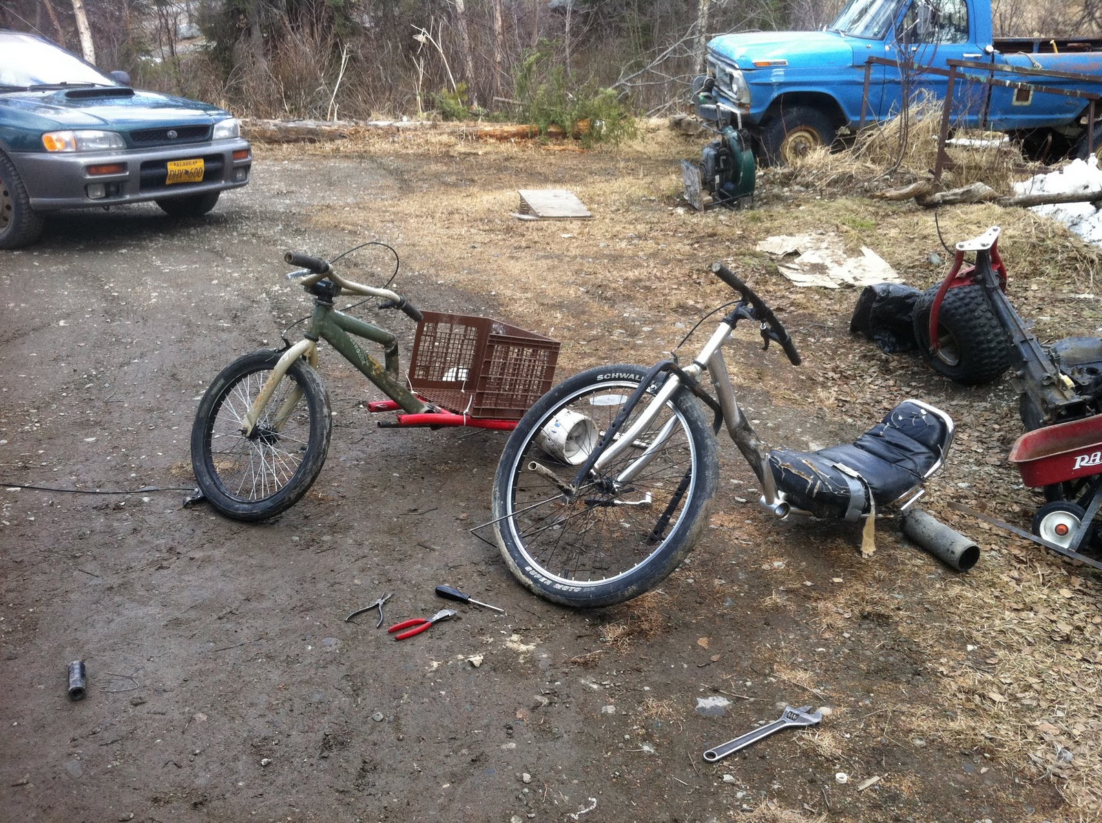
Drift Trikes
Last spring my friend and I started making drift trikes. If you dont know what drift trikes are, there pretty much just "big wheels" for foolish teenagers. Instead of me typing a bunch of stuff to describe it completley and making us all go to sleep, heres a link.


 the skate wheels worked till we started loosing bearings.. so we moved on! the next wheels are covered in acetal, a hard brittle plastic. the wheels were actually mass produced for a FIRST robotics challenge, so they didn't take too big of a bite out of my wallet.
 On the first run we hit some gravel roads doing 30+ mph and totally destroyed the new wheels. big rocks just hit the brittle plastic and took big chunks out of it. conveniently, they have an outside diameter of 6 inches so I just sleeved them with 6" Pvc pipe. the Pipe is attached with countersunk drywall screws.
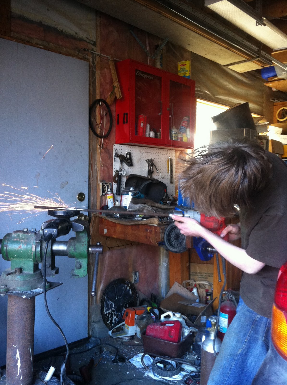
After all this, it was decided it was time for a version #2! this one is much smaller and made from a bmx bike rather than a mountain bike. a fundamental difference between the first and second trike was that the first had independley spinning wheels while the second had a live axle. The live axle was made of a peice of 5/8 inch rebar spun down to size on a improvised lathe. (drill and angle grinder)
 the second trike is in the back. the rear portion is made of a bent pair of forks from a crashed three wheeler with a split rim from a scooter acting as the bearing blocks. the rear tires are 6" pvc mounted on lawnmower rims.

here it is in action! The front wheel is changed out because the first one had a bent rim. the new one is from a minibike.

Anyways, we built some! the first started with a cut up bike that was pulled out of a trash pile, with some 3 inch abs pipe wheels mounted on cut up lawnmower rims.

notice how the frame is kinked, we thought we should change the rake for better drifting, but it ended up dropping the entire bike too low and the frame scraped when the wheel was turned too far. eventually, a second kink was added.
one run, the bearings in the rear wheels got hot enough to melt the plastic hubs. cannibalized skateboard to the rescue!


After all this, it was decided it was time for a version #2! this one is much smaller and made from a bmx bike rather than a mountain bike. a fundamental difference between the first and second trike was that the first had independley spinning wheels while the second had a live axle. The live axle was made of a peice of 5/8 inch rebar spun down to size on a improvised lathe. (drill and angle grinder)

here it is in action! The front wheel is changed out because the first one had a bent rim. the new one is from a minibike.

Steam Engine Post #1
Im making a steam engine in my Jewlery class, heres the fly wheel. all the other peices are in the shop, but heres a picture of the fly-wheel
 its all made from bent copper sheet.

Underwater ROV
This is an ROV ("Remotely Operated Vehicle") that I made out of PVC and assorted hardware. Underwater Rovs are used for search and rescue, underwater repair, and anything else where a robot can be substituted for a human in a sub-par "this place sucks, why am I here doing this?" type of environment. My ROV is small and more like a toy than a tool, but hey.
 Its on a 45' cat five tether, and controlled via 4 double pull double throw switches. The rov itself has six motors. with 4 pairs of wire in the cat 5 and six motors, there had to be some sneaky wiring done. The motors are synced in pairs of 3. for example, if the "left" switch is thrown, the left motor comes on. the right switch, the right motor. however, when both switches are thrown in the same direction a 3rd motor comes on. I really didnt think of it at the time, but it probolay dosent help with power consumption as 1 motor probolay maxes out the 24 gauge wire.. haha. theres also some leds that come on in different colors depending on direction of thrust. heres the controller. its a 4" PVC end cap. The two tanks on the top of the the wing create near-neutral buoyancy.
 heres some more pictures of the ROV


Monday, November 21, 2011
Gokart
This Is a gokart that I built last year. It started off during the summer of 2010 when I took summer school classes at the vocational school. I had welding in the morning and Small engines in the afternoon. In our small engines class the project was to put a gokart together out of a kit so that the school could sell it for fundraising or something. Halfway through the course, I had what i thought was an excused absence of a week (at the school, if you miss more than 3 days, they drop you). anyways, i came back after a week long marine biology escapade and was told that i was essintaily expelled. bummer. Having nothing better to do, iIwalked the 2 miles in the rain over to the schools main office. I spoke with the higher powers at work, and was re-enrolled on the premise that I would be auditing the class.
The small engines teacher said that there were no more gokart kits to put together, ("thank goodness" I thought to myself) so he gave me the project of making an old gokart new again. the poor thing had been sketichily extended and ruthlesly crashed, so I spent a week in welding making it stronger and closer to true. I then put a 1950's snowmachine engine on it. It worked great for about 10 minutes of burnouts and wheelies. The fun came to an end after a half inch shaft going into a lawnmower transmission that I had rigged up sheared. bummer. again. at the end of the course, the small engines teacher came up to me at the end of class and said, "well Dewane, you dont get a grade, but you get a gokart. get that hunk of junk out of here" anyways, I got a free gokart and engine and whatnot! Ive looked for pictures of it in this stage, but cant find any.
At home, I rebuilt it all. the snowmachine engine got replaced by a 125cc, 4 speed transmission three wheeler engine. It also got bigger tires and an aluminum gas tank. Heres some photos and videos!
My Hi-Tech Paint Booth

My Hi-Tech frame straghtiner.
 Done!
Done!
 Driving around and popping wheelies!
The small engines teacher said that there were no more gokart kits to put together, ("thank goodness" I thought to myself) so he gave me the project of making an old gokart new again. the poor thing had been sketichily extended and ruthlesly crashed, so I spent a week in welding making it stronger and closer to true. I then put a 1950's snowmachine engine on it. It worked great for about 10 minutes of burnouts and wheelies. The fun came to an end after a half inch shaft going into a lawnmower transmission that I had rigged up sheared. bummer. again. at the end of the course, the small engines teacher came up to me at the end of class and said, "well Dewane, you dont get a grade, but you get a gokart. get that hunk of junk out of here" anyways, I got a free gokart and engine and whatnot! Ive looked for pictures of it in this stage, but cant find any.
At home, I rebuilt it all. the snowmachine engine got replaced by a 125cc, 4 speed transmission three wheeler engine. It also got bigger tires and an aluminum gas tank. Heres some photos and videos!
My Hi-Tech Paint Booth

My Hi-Tech frame straghtiner.


Sadly, we took it off some jumps this summer and broke the axle. Its yet to be fixed!
Metal Art
Copper Bird
I built this out of some copper wire that I stripped. I think it was originally supposed to be a flower or something, but creativity happens

Railroad Spike Animals
I have a friend that used to be into making metal art. a few summers ago, he asked for my help getting this large piece of steel into his truck.I gladly agreed to help, and the next thing I knew, we were in a railroad yard with a large piece of half inch plate and five gallon buckets full of railroad spikes in the back of the truck. Cool!... right? Well apparently (according to the renta-cop) we didn't exactly have the permission to be there. long story short, we were told to put the plate back, but to take all the used spikes that we wanted. that summer, there was a plethora of railroad spike based art made, but this is all I could find around the house.


Globe Dude
I started taking a jewelry class this year in school, and this is one of the things that I have made. It started as just a brass ball, then it turned into a globe, then it turned into a goodie-box, then there was a copper-wire man to hold it. I made it by cutting out two brass circles, pounding those into hemispheres with dapping cubes. I then painted on the continents with tar, and submerged the globe in nitric acid. the acid dissolved the copper in the brass that wasn't covered with tar, essentially raising the continents. Finally, I put a band on the inside to hold the two halves together, yet still be able to open it.


Birthday Bird
I built this with my friends little brother for his sisters birthday. The bird is made of bicycle spokes, its supported by a piece of bike chain welded in place, and it all rests on a cut out of Alaska.

Friday, November 4, 2011
Lego Robot
I used to be really into Lego robotics. this is a robot from the 2007/2008 Power Puzzle challenge. It started out as something simple that was supposed to be kept simple, but when I started tinkering with pneumatics and pto's, things just got out of hand and I ended up with this.


Subscribe to:
Comments (Atom)
